Table of Contents (click to expand)
The main reason Ethernet cables are twisted is to reduce noise. This is because twisted cables are less susceptible to electromagnetic interference (EMI) from other sources. Additionally, when the cables are twisted, it helps to equalize the exposure to noise sources, which helps to cancel out the noise when the signals are received.
Turn around a router and you’ll find a peculiar wire plugged into its back. The wire bears an eerie resemblance to a snake: it has a small head and a long, shiny body. When you unplug its teeth from the router’s flesh, a dull clink can be heard. Its head is transparent and underneath its skin, you’ll find multiple wires, of different colors, twisted and coiled together to form a single conductor, the Ethernet.
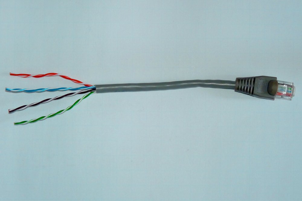
It is these ribbons of wires braided together that provide the router and therefore your devices with Internet access. However, isn’t it strange that these wires, which connect your router to the Internet Service Provider (ISP) miles away, must not be laid grouped like bristles, but rather twisted around each other?
Recommended Video for you:
The Reduction Of Noise
No engineer would meddle with equipment unless the meddling reaps some benefit. The colorful wires aren’t twisted because the conductor looks quirky; they are twisted to curtail undesirable noise signals.
Alexander Graham Bell was the first person to realize the advantages of transmitting signals in twisted wires. Although the telephonic wires weren’t twisted so intricately or extensively as they are today. The pair of wires transmitting or receiving telephonic signals would be twisted, or their positions would be swapped on every pole. These poles were separated by equal distances and were stacked along for several kilometers. The pole, which is now a relic from a glorious era of scientific discoveries and innovations that witnessed the birth of what one would now call “premodern” or even “modern” technology, can still be found in rural areas.
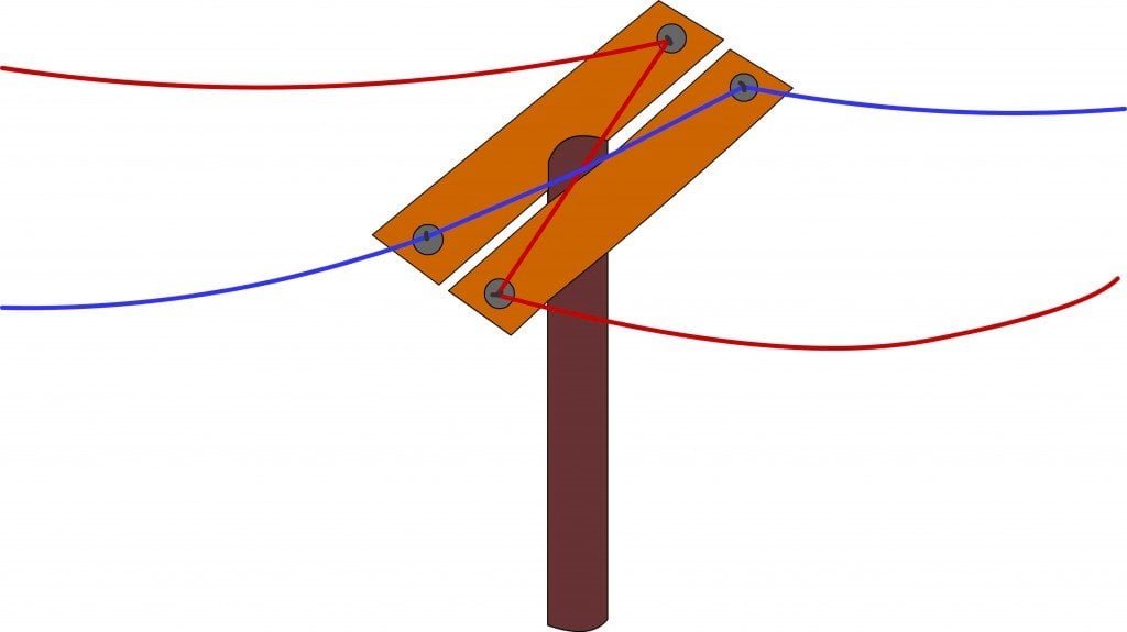
The signals transmitted on the two wires were equal in magnitude, but opposite in polarity. Therefore, if one wire were to carry a signal of voltage +A, the wire parallel to it would carry a signal of voltage -A. These are called differential signals because the output a receiver produces upon receiving them is the arithmetic difference of these signals. The receiver subtracts A and -A to generate 2A. However, why is this so nifty?
It is only in the ideal world that the receiver receives the two signals A and -A without any noise. The environment will inevitably introduce noise into the wires and corrupt the signals. However, noise signals are introduced without any reversal of polarity: the source of noise induces a voltage component in both wires, say, +N, and not +N and -N. Therefore, the corrupted signals the receiver now receives are (A+N) and (N-A). However, because it subtracts both inputs, the output generated is absolutely free of noise as (A+N) – (N-A) = 2A.
This was undeniably brilliant. However, it’s based on a fallacy. It is based on the assumption that the noise induced in the two parallel wires is equal in magnitude. This is certainly untrue, for the source might not be equidistant from the two wires. One wire would then be exposed to more noise than the other. How can one solve this problem?
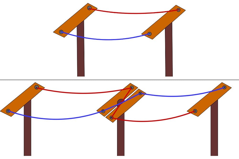
Well, one way to solve it is to expose the other wire to more noise, making the two components equal. If the two wires are regularly exposed to the source of noise turn by turn, the magnitude of noise induced in them would also be the same. This can be achieved by – believe it or not – twisting or swapping the wires!
Electromagnetic Interference (EMI)
A century later, wires aren’t thick and taut between tall poles; instead, they are extremely thin and are found often taut or sprawling between small, oddly shaped boxes. And yes, another thing, the boxes and the wires connecting them are everywhere.
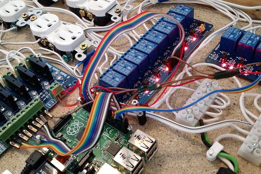
The challenge that so many, closely situated wires presents engineers with is that now noise in a wire isn’t just induced by the environment, but also by other wires in its vicinity. Moving electrons, just like those that constitute a current in a conductor, radiate electromagnetic waves. The electromagnetic waves produced by one wire can disturb the electrons in the wire beside it. As EM waves comprise oscillating or changing magnetic fields, an EM wave traversing a wire can induce a current in it. This is called cross-talk and this type of noise is called electromagnetic interference (EMI).
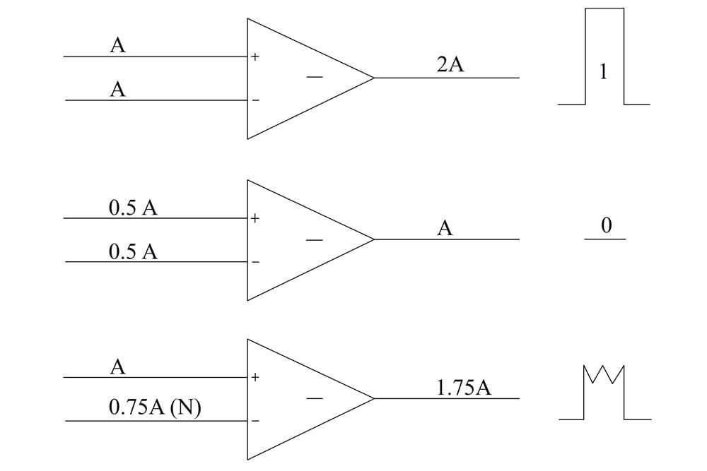
EMI is particularly disconcerting today when signals aren’t analog, but digital, and when communication signals are not carried on sinusoidal waves, but rather translated into a binary language of 0s and 1s, the only language a computer can understand. However, essentially, binary signals are standardized analog signals: if a voltage of A translates to a ‘0’, then 2A translates to a ‘1’.
Now, if environmental noise and EMI induce voltage components indiscriminately, that is, the noise imparted in the two wires is not equal in magnitude, the output is certainly less than 2A. The computer now finds differentiating between 0 and 1 quite difficult and is liable to confuse the one for the other, thereby producing horribly erroneous results.
Extensive braiding curtails (in reality, absolute elimination is impossible) noise in two ways: first, as explained, equal exposure to the source ensures that most of the noise is canceled when the signals are subtracted by the receiver; and second, at each and every twist, the magnetic field produced by the wire changes its polarity, such that the currents induced are opposite in polarity, which ultimately, of course, negate each other to produce effectively noise-free signals. Effectively, but not completely.
To further improve the signal’s clarity, wires are thickened or thinned, better insulated, or their number of twists and turns are varied according to the application. However, you will rarely, if ever, find them unraveled or untwisted.


