Table of Contents (click to expand)
A speedometer is prone to mechanical errors, whereas GPS works by calculating the time it would take to travel from point A to B, making them the more accurate option.
The other day, a friend and I rode a routine bike to the nearby hill station. The ride was great, as always—the scenic road, the wind blowing past us as we rode, and the snack stop en route. Everything felt just right. We were cruising on an empty straight road and had a little race. Whoever crossed the 100 kmph mark first would win 100 bucks. Simple, no? Well, not quite. My friend was the first to hit the 100 kmph mark on his speedometer. He slowed down when he saw the pointer on his speedometer hit 100.
As a mechanical engineer, I know speedometers are pretty inaccurate and went a little overboard. I blazed past him, speeding at over 110 kmph, to which he objected, claiming that he had won the race. I had to explain the frequent inaccuracy of speedometers and my preference for GPS. He wasn’t happy with my argument, but he eventually gave me the win.
The question is, why are speedometers inaccurate?
Recommended Video for you:
How Do Speedometers And GPS Devices Measure Speed?
To understand why a speedometer provides slightly inaccurate readings, we first need to know how speedometers and GPS devices measure speed. The speedometer on your vehicle can be either an electronic one or a mechanical one. Mechanical speedometers have existed since the 1900s, whereas the automotive world didn’t see the first all-electronic speedometer until the late 1980s. Most modern vehicles use an electronic speedometer to gauge and display the vehicle’s speed.
Mechanical Speedometer
Mechanical speedometers are simple in construction and consist of the following parts: drive cable, magnets, speed cup, a hairspring, and the terminal pointer needle on the dashboard. The drive cable is a flexible cable (a collection of small helical coil springs tightly wound around a central wire or mandrel) attached to the vehicle’s transmission. To be more precise, the drive cable is connected via a small pinion gear to the gear wheel on the transmission’s output shaft. The output shaft is connected to the vehicle’s wheels and imparts its rotational speed to them. Thus, connecting the drive cable of the speedometer to the output shaft provides a relatively accurate assessment of the vehicle’s speed.
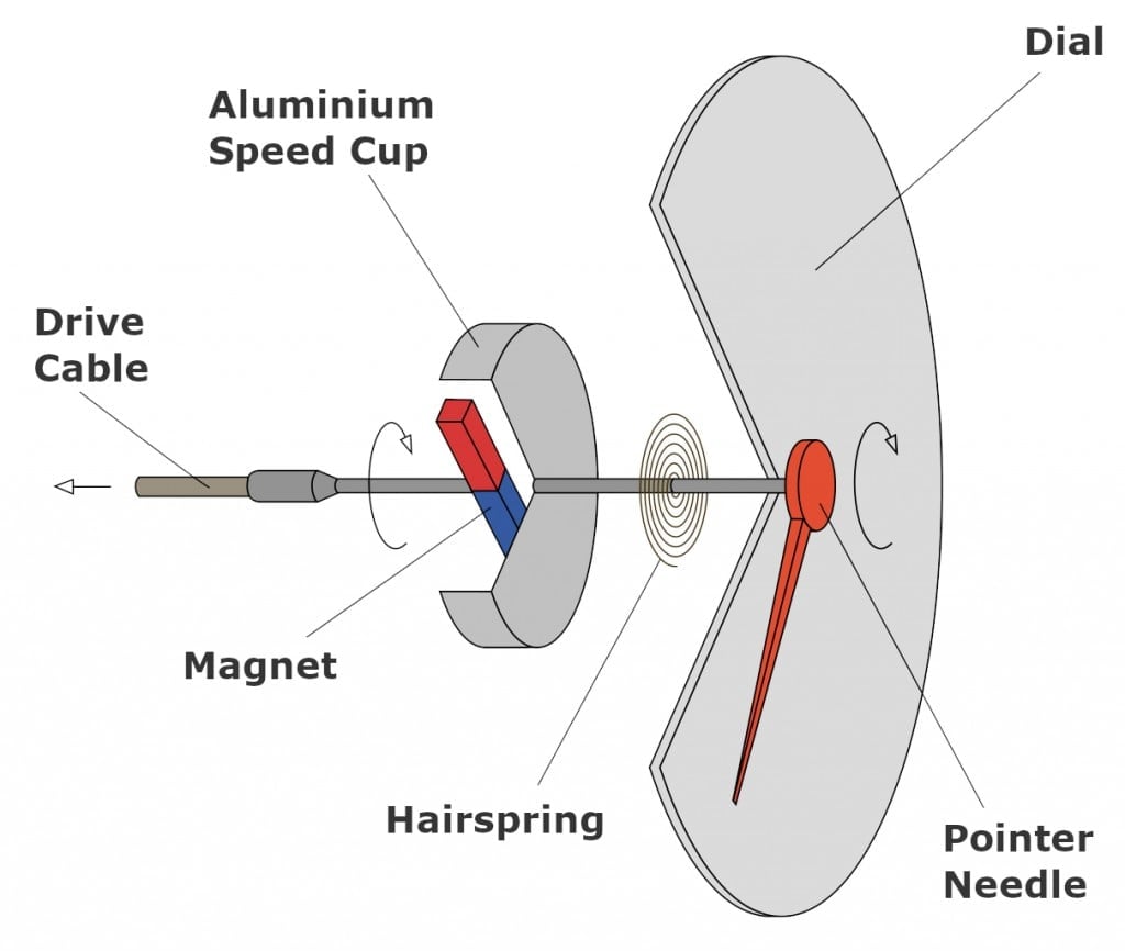
When the vehicle is in operation, the rotary motion of the output shaft is carried over to the central mandrel of the drive cable. The drive cable, therefore, starts rotating at the same speed as the output shaft, which rotates at the same speed as the vehicle’s wheels. The other end of the drive cable connects to a magnet, which sits inside the speed cup. The magnet does not touch the interior of the speed cup, as a certain air gap is maintained between the two.
The rotary motion of the drive cable is imparted onto the magnet. As a result, the magnet creates a rotating magnetic field around itself. The rotating magnetic field induces small eddy currents in the speed cup. The torque of these eddy currents forces the speed cup (and, consequently, the pointer needle) to rotate in the same direction as the magnet.
The faster the output shaft rotates, the greater the strength of the magnetic field, forcing the speed cup and the pointer needle to move farther along the speed dial. The hairspring is present to resist the speed cup’s torque and hold the pointer at zero when the vehicle isn’t operating. The pointer needle stops turning when the opposing torque of the hairspring equals the torque due to eddy currents; and points towards a correct speed value on the dial.
Electronic Speedometer
Electronic speedometers are even simpler than their mechanical counterparts. A rotational speed sensor (also called a vehicle speed sensor) is mounted on the transmission’s output shaft. It transmits electronic pulses corresponding to the rotation speed of the shaft.
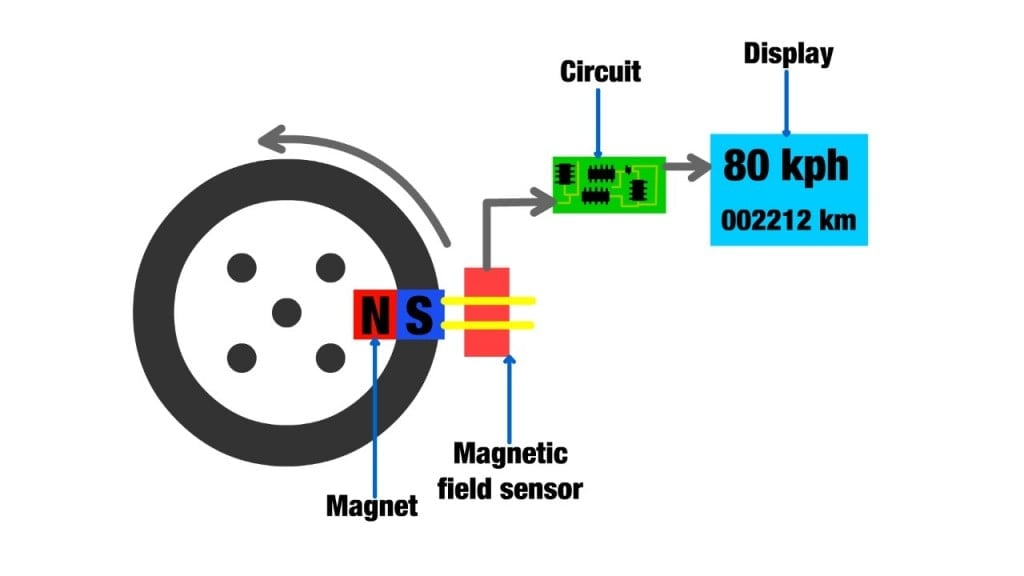
The sensor setup consists of a metal disk with tiny teeth enclosed by a circular magnet. When the shaft spins, the teeth obstruct the magnetic field being picked up by the magnetic field sensor. These pulses are counted by a computer and compared to the total number of turns of the wheels, consequently giving the car’s speed.
GPS
A GPS device calculates speed in the easiest way possible. These tools use the classic ‘speed = distance/time’ formula to measure speed. A GPS device tracks the vehicle’s location over time and measures the distance the vehicle has traveled. To know precisely how the distance is calculated and how global positioning systems work, head on to “How Does Global Positioning System (GPS) Work?“.
The distance traveled value is then divided by the time it took the vehicle to travel between the two points/locations. The resulting number indicates the speed at which the vehicle traveled between the two points. Given that GPS devices use a vehicle’s position to calculate its speed, they are also called positional speedometers.
Speedometers Vs. GPS
Speedometers are composed of many mechanical parts and are prone to mechanical errors. The speedometers also measure speed by indirectly being in contact with the tires. Thus, a change in any property of the tires results in an inaccurate reading. The most common example is a change in the dimension of the tires, followed by tire pressure, normal wear and tear, temperature, and load.
Manufacturers calibrate speedometers for the tires installed by them. Still, when a customer changes the pre-installed tires or uses a set of tires other than the official recommendation, the speedometer needs to be recalibrated, or else the speed reading will be inaccurate.
For safety reasons, manufacturers calibrate speedometers to read higher than the vehicle’s actual speed. A higher value alerts the driver about the speed and prevents them from speeding. However, there is a limit on how high or low a speedometer can read. Speedometers are not allowed to read lower than the actual speed of the car, but they are permitted to indicate a value 10% higher than the actual speed, plus 4.
On the other hand, GPS uses a purely mathematical technique to measure the vehicle’s speed and is, therefore, more accurate than a speedometer. That being said, GPS comes with a catch too. GPS devices work best when the vehicle travels straight and has an uninterrupted sky view. A clear view is important, as the GPS receiver needs to interact with satellites. Also, when the vehicle travels on the road with multiple twists and turns, GPS cannot predict how tight a turn was made. Thus, even GPS readings cannot always be trusted.
Another shortcoming of a GPS device is that it fails to provide the instantaneous speed of the vehicle; it only gives the average speed with a slight delay.
Conclusion
Honestly, the difference in accuracy between a speedometer and a GPS device isn’t huge. For example, the speedometer might display your speed as 100 kmph, but GPS, being the more accurate of the two, knows the true speed and would display a value in the neighborhood of 92 kmph. This difference arises due to mechanical errors and the handicaps set by the manufacturers. These techniques and the inaccurate readings of a speedometer are often a blessing in disguise, as they prevent drivers from driving recklessly or getting tickets all the time!


